Other articles on hexapod applications can be found here.

Hexapod Parallel Kinematics Update
There are many new developments for parallel kinematic multiaxis positioners. The video below explains some of the differences between serial and parallel kinematics.
Other articles on hexapod applications can be found here.
Other articles on hexapod applications can be found here.
See you at the Pathology Visions Conference

Advances in high-throughput, high-reliability focus automation for digital pathology
Scott Jordan
Director, NanoAutomation Technologies
PI (Physik Instrumente) L.P.
scottj@pi-usa.us
Broad adoption of digital pathology depends upon reliable and repeatable slide digitization. In turn, repeatable/reliable whole slide imaging depends upon the ability to quickly find, hold and track focus. We discuss recent advances in piezoelectric focusing mechanisms and associated metrology of relevance to the community.
High-speed, high reliability focus optimization plays an important role in digital pathology by enabling faster capture of more repeatable images, by maintaining crisp focus during slide scanning motions, and by enabling real-time tracking over the acquisition intervals required by some emerging microscopy techniques. These attributes make focus automation a key variable in diagnostic concurrence.
Of the mechanical approaches available, piezo-actuator driven focus mechanisms combined with through-optic laser sensors offer the high-speed and high reliability required for meeting emerging demands. Piezo actuator driven mechanisms provide sub-millisecond response and can keep pace with throughput-driven methodologies. Thus they can improve process economics in digital pathology as they have in applications like gene sequencing, semiconductor lithography and interferometric metrology.
Here we review:
Scott Jordan
Director, NanoAutomation Technologies
PI (Physik Instrumente) L.P.
scottj@pi-usa.us
Broad adoption of digital pathology depends upon reliable and repeatable slide digitization. In turn, repeatable/reliable whole slide imaging depends upon the ability to quickly find, hold and track focus. We discuss recent advances in piezoelectric focusing mechanisms and associated metrology of relevance to the community.
High-speed, high reliability focus optimization plays an important role in digital pathology by enabling faster capture of more repeatable images, by maintaining crisp focus during slide scanning motions, and by enabling real-time tracking over the acquisition intervals required by some emerging microscopy techniques. These attributes make focus automation a key variable in diagnostic concurrence.
Of the mechanical approaches available, piezo-actuator driven focus mechanisms combined with through-optic laser sensors offer the high-speed and high reliability required for meeting emerging demands. Piezo actuator driven mechanisms provide sub-millisecond response and can keep pace with throughput-driven methodologies. Thus they can improve process economics in digital pathology as they have in applications like gene sequencing, semiconductor lithography and interferometric metrology.
Here we review:
- Four types of piezo actuators
- Reliability and speed capability of piezo actuator driven focus mechanisms
- Focus detection technologies often used with piezo mechanisms
- Examples of piezo deployment for high speed focus in other industries
- Key metrics for evaluating and selecting focusing technologies
New Technology Enables Focusing from Afar
When most people hear the word "piezo" in the context of motion control, they understandably think of the classical piezoelectric stack actuator, composed of hundreds of thin layers of specialized ceramic interleaved with electrodes and sintered together. When a voltage is applied, the stack expands. Expansion is limited to about 1% of the stack length-- thus, a 100 mm long stack provide about 100 microns of travel. Clever, frictionless lever amplifiers can be fabricated (usually using sophisticated wire electric discharge machining) to provide magnified travel. In this way a compact piezo stage can provide hundreds of microns of travel.
This basic approach has served the microscopy industry well over our many years of manufacturing our popular PIFOC™ objective positioners, specialized linear motion devices optimized to tuck unobtrusively into a turret assembly while providing fast and straight axial positioning of the objective. However, microscopes' dimensional constraints limit the amount of lever amplification such devices can incorporate. 400 microns has traditionally been the limit for PIFOCs in our catalog.
Until now. Over the past several years, we've engineered new piezo technologies which provide much longer travels. Rather than rely on the simple expansion and contraction of the ceramic element, our various piezomotors utilize either ultrasonic linear actuation or various approaches to walking actuation. Each piezomotor principle has its inherent strengths for target applications but all provide theoretically unlimited travel, fieldless operation, high stiffness and holding force, nanoscale position-hold stability over long periods, and compact size.
Our NEXACT® motors, part of our PiezoWalk® family of ceramic motors, are an excellent example of all the above, plus sub-nanometer resolution. Their small size and impressive force makes them ideal for long-travel objective positioning, and they are at the heart of our new N-725 NEXACT PIFOC Objective Positioner. Offering a full 1 mm of travel, this unique mechanism offers high speed and maintenance-free operation. Its long travel helps accommodate varying substrates and easy load/unload operations, making it ideal for automation applications. And now it is available in systems integrating the Motion X FocusTrac™Autofocus Sensor for especially responsive and crisp autofocus actuation.
Meanwhile, autofocus is now a capability which spans almost all PI motion device and controller combinations. Ease-of-use, stability, speed, applications flexibility and reliable focus capture from extreme out-of-focus conditions were notable design targets accomplished with all configurations. Systems integrating N-725 meet all these criteria over the full 1mm range of the device. Its sophisticated, all-digital E-861 Controller/Driver offers USB and RS-232 connectivity together with TTL utility and trigger lines and a joystick port. And, as a PI General Command Set device, it is supported by a wealth of proven software development tools and the leading microscopy suites.
A special capability is Fast Focus & Freeze (F3), PI's exclusive ability to capture and track the focal plane and then bumplessly switch to nanoscale-stable position-hold, with the ability to precisely position the objective with respect to the focal plane using the device's integrated position sensor. This is an invaluable capability for high-throughput automated Z sectioning and other quantitative studies where the focal plane serves as a datum plane. With N-725, F3means the initial condition can be up to 1 mm out of focus.
Count the enablers: unprecedented travel, easy integration, high responsiveness, fast actuation, robust focus-capture and tracking, and Fast Focus & Freeze. N-725 is a revolutionary addition to the microscopist's toolkit.
Until now. Over the past several years, we've engineered new piezo technologies which provide much longer travels. Rather than rely on the simple expansion and contraction of the ceramic element, our various piezomotors utilize either ultrasonic linear actuation or various approaches to walking actuation. Each piezomotor principle has its inherent strengths for target applications but all provide theoretically unlimited travel, fieldless operation, high stiffness and holding force, nanoscale position-hold stability over long periods, and compact size.
 |
| N-725 PIFOC® is the first piezo-objective drive with integrated NEXACT® Piezo Linear Motor, combining smooth motion, long travel ranges and fast response with extreme position stability |
Our NEXACT® motors, part of our PiezoWalk® family of ceramic motors, are an excellent example of all the above, plus sub-nanometer resolution. Their small size and impressive force makes them ideal for long-travel objective positioning, and they are at the heart of our new N-725 NEXACT PIFOC Objective Positioner. Offering a full 1 mm of travel, this unique mechanism offers high speed and maintenance-free operation. Its long travel helps accommodate varying substrates and easy load/unload operations, making it ideal for automation applications. And now it is available in systems integrating the Motion X FocusTrac™Autofocus Sensor for especially responsive and crisp autofocus actuation.
 |
| N-725 tracking focus of a disk spinning at 300 RPM |
 |
| Fast, automatic focus capture from 900 microns out of focus! |
Count the enablers: unprecedented travel, easy integration, high responsiveness, fast actuation, robust focus-capture and tracking, and Fast Focus & Freeze. N-725 is a revolutionary addition to the microscopist's toolkit.
Tip: How to Ensure the Best Resolution in Analog Interfacing
A large portion of our customers' nanopositioning applications utilize analog interfacing for position-command. As we have discussed before, analog interfacing offers many compelling benefits including high speed, easy synchronizing, compatibility with our patented HyperBit DAC-resolution enhancement, straightforward generation of complex waveforms, and ready compatibility with external-sensor and tracking schemes.
But occasionally we will encounter a customer application where the analog-interfaced nanopositioning system isn't providing the resolution the customer expects. Most often, this is due to a simple issue: a mismatch between the voltage range of the customer's digital-to-analog converter (DAC) and the voltage range of the position-command input on the nanopositioner.
Consider the case where a 16-bit DAC (such as is common on multifunction cards installed in the customer's computer) offers a -10 to +10V range, but the input to the nanopositioner has a 0 to 10V range. The card's "16-bit"ness means that its 20V range is spread over 216 steps... that's 65,536 steps. So the voltage resolution is 20 ÷ 65536 = 0.3mV. If the card were set to provide a range of 0 to 10V, then its resolution would be 10 ÷ 65536 = 0.15mV ...in other words, the resolution would be improved by a factor of two. The mismatch means an entire bit of resolution is lost!
Many (but unfortunately not all) multifunction analog I/O cards offer a configuration option (accessible, for example, via National Instruments' Measurement and Automation Explorer utility, NI-MAX, or via NI-DAQmx subVIs in LabVIEW) for setting the analog range of the DAC. Certainly, any application benefits from matching the analog ranges as closely as possible. For those occasions when it is not supported by the hardware, consider HyperBit as a way of recovering that lost bit... and many more.
Read these papers for the latest on high-througput digital interfacing.
But occasionally we will encounter a customer application where the analog-interfaced nanopositioning system isn't providing the resolution the customer expects. Most often, this is due to a simple issue: a mismatch between the voltage range of the customer's digital-to-analog converter (DAC) and the voltage range of the position-command input on the nanopositioner.
Consider the case where a 16-bit DAC (such as is common on multifunction cards installed in the customer's computer) offers a -10 to +10V range, but the input to the nanopositioner has a 0 to 10V range. The card's "16-bit"ness means that its 20V range is spread over 216 steps... that's 65,536 steps. So the voltage resolution is 20 ÷ 65536 = 0.3mV. If the card were set to provide a range of 0 to 10V, then its resolution would be 10 ÷ 65536 = 0.15mV ...in other words, the resolution would be improved by a factor of two. The mismatch means an entire bit of resolution is lost!
Many (but unfortunately not all) multifunction analog I/O cards offer a configuration option (accessible, for example, via National Instruments' Measurement and Automation Explorer utility, NI-MAX, or via NI-DAQmx subVIs in LabVIEW) for setting the analog range of the DAC. Certainly, any application benefits from matching the analog ranges as closely as possible. For those occasions when it is not supported by the hardware, consider HyperBit as a way of recovering that lost bit... and many more.
Read these papers for the latest on high-througput digital interfacing.
- Interfacing Fast Nanopositioners to Track-Following Servos
- High-speed, low latency communications for nanopositioning in Single-Molecule Biophysics
Introducing Digital Control at an Analog Controller Price
 |
| High Resolution Digital Servo Piezo Controller at Analog Price |
PI's groundbreaking E-709 Compact and Cost-Optimized Digital Piezo Controller leverages the very latest in digital electronics technology for dramatic value and performance. The unit features a very compact, panel-mount package and includes USB and analog interfaces for position commands and sensor monitoring as well as SPI for real-time interfacing in demanding industrial and research applications.
Despite its small size and analog-controller price, E-709 packs a host of features formerly found only on much costlier digital controllers:
- A 10W peak-power amplifier
- TTL utility interfaces for synchronization, triggering and signaling
- A built-in data recorder
- An internal waveform generator
This is a true digital controller, with a digital servo based on sophisticated, real-time algorithms. Beware the tendency of some to call any controller with communications interfaces "digital"! In a digital servo, gains and other parameters are software-settable, and the system is immune to DAC drift since the DAC resides inside the servo loop. And like all PI digital controllers, E-709 offers plug-and-play auto-calibration with our closed-loop nanopositioners. It is available in versions for PI nanopositioners with capacitive sensors or strain gauge and piezoresistive sensors, for which it offers unprecedented 5th-order digital linearization.

E-709 runs on any 24VDC source, making it ideal for OEM applications. In fact, an unpackaged version for OEM applications offers special cost-effectiveness. OEMs will also appreciate the supportability benefits of the software-settable servo parameters and plug-and-play automatic calibration. Research and industrial users alike will appreciate its utilization of PI's General Command Set, so applications written for any PI controller may be readily adapted to E-709 and vice versa. A host of software functionality is also supported, including comprehensive LabVIEW libraries and Windows .dll and Linux .so libraries.
E-709 is also ideal for autofocus applications ranging from research microscopy to industrial inspection, scanning and even the latest genomics applications. For example, it interfaces in real time with Motion X's superb FocusTrac through-optic focus sensors, providing precise, stable snap-in on the order of tens of milliseconds. It is compatible with our full line of classical PIFOC objective positioners and sample-positioning Z stages. It provides responsive real-time tracking, and it supports PI's unique Fast Focus & Freeze capability, where the unit can be bumplessly switched from external (focus) sensor to internal (capacitive, SGS or piezoresistive) sensor, allowing precise, calibrated, stable motions with respect to the focal plane.
E-709 offers a peek at the future of nanopositioning today, at an affordable price.
More reading on nanopositioning.


Attack the Stack
Hexapods advance motion capabilities beyond convention
Multi-axis motion has conventionally been achieved by bolting-together multiple linear and rotary stages. And (speaking as a leading manufacturer of linear and rotary stages) this can certainly be an effective approach we thoroughly endorse.
But hexapods take multi-axis motion control to another level entirely:
PI has many years of experience in designing and manufacturing hexapods for the world's most demanding applications. As a consequence, PI makes more hexapods than all competitors combined. Our experience benefits your application with superior performance, reliability, software and global support. PI hexapods range in size from smaller than a coffee can to the size of a small car. If you don’t see what you need for your application, count on responsive support from a PI applications engineer at any of our worldwide offices.
Read more articles about Hexapod applications

Multi-axis motion has conventionally been achieved by bolting-together multiple linear and rotary stages. And
 (speaking as a leading manufacturer of linear and rotary stages) this can certainly be an effective approach we thoroughly endorse.
But hexapods take multi-axis motion control to another level entirely:
- PI hexapods' highly triangulated configuration and proprietary joint design results in greater stiffness than any stack of stages can provide. For example, the resonant frequency of our M-850 hexapod--our original model--with a substantial, 10kg load exceeds 90Hz transversely and 500Hz axially-- meaning this six-degree-of-freedom positioner when significantly loaded has a higher resonant frequency than many single-axis stages, unloaded!
- Parallel kinematics means a PI hexapod’s six stiff linear actuators share the load of the moving platform, and their loading is purely axial, maximizing their stiffness. By comparison, with a stack of stages, only the top stage supports the load… the next stage supports the load and the top stage; the next stage supports the load and the top stage and the next stage… and so on, down to the bottom stage in the stack, which supports the load and all the other stages. This is a key reason for the superior stiffness and higher resonant frequency of hexapods, with direct impact on system responsiveness.
- You need never tune a PI hexapod. On the other hand, each of the axes in a stack of servo stages will have its own tuning requirements, and optimizing for your load can be a significant chore for stacked configurations and can even risk damage.
- Well-designed hexapods have no moving/sweeping cables to rub, wear and foul. After all, cabling tends to be the most unreliable part of conventional motion systems, so this advantage goes directly to reliability and
MTBF. In addition, cable-borne vibration, rubbing and tugging will inevitably reduce the minimum incremental motion, repeatability and stability of stage stacks.
However, not all hexapods are created equal-- you will find some manufacturers whose cables drape and dangle, forming an untidy mess all the way to the controller. Besides raising reliability and stability issues, this is an invitation to electromagnetic interference. PI’s popular hexapods have exactly two cables going from high-quality connectors on the hexapod's base to the controller: one for the hexapod’s integrated, high-efficiency drive amplifier (no extra box required), and the other for control signals. Each cable has one connector on each end, for simple and reliable connections and painless setup.
- The center-of-rotation for rotation stages and goniometers are fixed in space. By comparison, the center-of-rotation for PI hexapods may be placed anywhere in space with a single, simple software command. And, PI hexapods speak in human units: millimeters for the X, Y and Z axes (with resolution to 0.1 micron) and degrees for the pitch, yaw and roll axes (with resolution to 0.1 millidegree). This is all kept easy-to-use by the sophisticated digital controller which transparently handles all the coordinate transformations.
- PI hexapod controllers offer advanced microrobotic capabilities like automatic vectoring and our General Command Set, which is both inherently multi-axis and easy-to-use. Powerful macro capabilities are built-in.
Comprehensive and well-documented LabVIEW libraries, Windows .dll and Linux shared object libraries come standard and support the instrument’s high-level multi-axis capabilities, yet the sophisticated mnemonic command set can be utilized directly if desired. Up to two additional axes of servo-controlled motion can be optionally provided by the controller. Two channels of optical or analog data acquisition can similarly be provisioned internal to the controller. RS-232 and TCP/IP interfaces are standard, with GPIB a cost-effective option. And PI hexapods provide a repeatable absolute coordinate system that is consistent from power-up to power-up; beware alternative configurations which rely on springs to support the load or address hidden backlash issues in the drivetrain.


PI has many years of experience in designing and manufacturing hexapods for the world's most demanding applications. As a consequence, PI makes more hexapods than all competitors combined. Our experience benefits your application with superior performance, reliability, software and global support. PI hexapods range in size from smaller than a coffee can to the size of a small car. If you don’t see what you need for your application, count on responsive support from a PI applications engineer at any of our worldwide offices.
Read more articles about Hexapod applications
How to Push a Rope: Enabling Accurate On-The-Fly Sectioning And Sampling with DDL
Any physical or electronic mechanism has finite bandwidth. One practical consequence of this for nanopositioning is often seen in waveform actuation: sharp corners get rounded, and phase lags begin to accrue. This fundamentally limits the accuracy of sampling and sectioning techniques which infer position from time. In such situations, the diminished dynamic accuracy from the following error which occurs as a consequence of finite system bandwidth can be a significant limiter for the application. As the old saying goes, "You can't push a rope."
Except, you can. Read on.
 For typical nanopositioning systems, the system bandwidth is limited by the resonant frequency of the loaded piezo stage; one-third of Fres is a reasonable rule-of-thumb for the bandwidth in such cases, and significant corner-rounding, attenuation and phase lags are seen well below this number. So, the obvious way to increase system bandwidth is to choose the stiffest (highest loaded Fres) stage (and, of course, reduce the load mass). However, the stiffness of the stage goes inversely as the square of the lever ratio of its integrated lever amplifiers, so high-Fres stages are typically limited in travel. The past few years have seen strikingly compact long-travel piezo stages become very popular; these achieve their long travel and small size through the use of novel lever amplifiers with high ratios, and one consequence is low Fres. An example is our P-629.1CD PIHera linear stage, which provides an amazing 1.5mm of closed-loop travel in a 100x100x22.5mm package, and a Fres of 110 Hz with a 120g load.
One way around the following error that inevitably results from finite system bandwidth is to sample position simultaneously with acquiring your other data using a deterministic, low-latency interface such as the analog, SPI or parallel I/O (PIO) interfaces offered on our controllers. This means you always know the exact position at which your data was acquired, so if the stage doesn't track your desired waveform perfectly at high speeds, it might not matter. A good example of a fast application enabled by this trick is our CyberAligner Modular Alignment Workstation targeted at characterization and packaging automation applications for waveguides and other fiber-coupled devices.
But this is not always an optimal solution. Perhaps the application demands that data be equally spaced in both position and time, or perhaps the quantity being measured can vary with instantaneous velocity (an example being current generated by moving a nanocoil probe over a sample containing small magnetic features). For such applications, there is no substitute to improving the fidelity of the position waveform. But conventional closed-loop servo technologies cannot address limited system bandwidth and often contribute significantly to it.
We offer two unique solutions:
A recent customer application spotlights this. The application required rapid but very precise scanning over the full 1.5mm range of the P-629.1CD stage, with precise TTL signals from the nanopositioning controller at specific points in the waveform to trigger other instrumentation. We approached this application using LabVIEW and DDL: First, the controller's internal waveform generator is enabled and the waveform parameters and TTL trigger-output specifications downloaded via our comprehensive standard set of LabVIEW subVIs, then waveform generation is commenced. We used our digital controller's built-in data recorder capability to verify the impact of DDL in this application. The figure shows the tracking performance of the loaded P-629.1CD before and after enabling DDL.
This has proven to be an enabling technology for this and other applications in fields as diverse as semiconductor metrology, defense and clinical life sciences, where rapid scanning requirements increasingly include previously unapproachable dynamic accuracies over long travels.
More information on Methods to Improve Piezo Dynamics
Except, you can. Read on.
One way around the following error that inevitably results from finite system bandwidth is to sample position simultaneously with acquiring your other data using a deterministic, low-latency interface such as the analog, SPI or parallel I/O (PIO) interfaces offered on our controllers. This means you always know the exact position at which your data was acquired, so if the stage doesn't track your desired waveform perfectly at high speeds, it might not matter. A good example of a fast application enabled by this trick is our CyberAligner Modular Alignment Workstation targeted at characterization and packaging automation applications for waveguides and other fiber-coupled devices.
But this is not always an optimal solution. Perhaps the application demands that data be equally spaced in both position and time, or perhaps the quantity being measured can vary with instantaneous velocity (an example being current generated by moving a nanocoil probe over a sample containing small magnetic features). For such applications, there is no substitute to improving the fidelity of the position waveform. But conventional closed-loop servo technologies cannot address limited system bandwidth and often contribute significantly to it.
We offer two unique solutions:
- Advanced Piezo Control, a proprietary servo algorithm which is optional on our top-of-the-line E-712 digital nanopositioning controller. This technology is ideal for virtually eliminating following error in tracking applications where the stage path is not predefined.
- Dynamic Digital Linearization, a technology available in most of our digital controllers (the link is to the "Methods to Improve Piezo Dynamics" article in our Piezo University). This technology can reduce the following error of repetitive scan waveforms down to the system noise level. For highly-leveraged stages with inherently low resonant frequency, the improved dynamic accuracy can be remarkable.
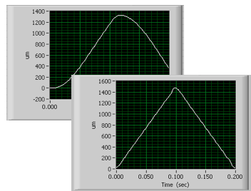 |
| Full 1.5mm piezo scan showing enhanced dynamic accuracy/reduced following-error from Dynamic Digital Linearization |
This has proven to be an enabling technology for this and other applications in fields as diverse as semiconductor metrology, defense and clinical life sciences, where rapid scanning requirements increasingly include previously unapproachable dynamic accuracies over long travels.
More information on Methods to Improve Piezo Dynamics
Subscribe to:
Posts (Atom)