How to Push a Rope: Enabling Accurate On-The-Fly Sectioning And Sampling with DDL

Any physical or electronic mechanism has finite bandwidth.  One practical consequence of this for nanopositioning is often seen in waveform actuation: sharp corners get rounded, and phase lags begin to accrue.  This fundamentally limits the accuracy of sampling and sectioning techniques which infer position from time.  In such situations, the diminished dynamic accuracy from the following error which occurs as a consequence of finite system bandwidth can be a significant limiter for the application.  As the old saying goes, "You can't push a rope."

Except, you can.  Read on.

For typical nanopositioning systems, the system bandwidth is limited by the resonant frequency of the loaded piezo stage; one-third of Fres is a reasonable rule-of-thumb for the bandwidth in such cases, and significant corner-rounding, attenuation and phase lags are seen well below this number.  So, the obvious way to increase system bandwidth is to choose the stiffest (highest loaded Fres) stage (and, of course, reduce the load mass).  However, the stiffness of the stage goes inversely as the square of the lever ratio of its integrated lever amplifiers, so high-Fres stages are typically limited in travel.  The past few years have seen strikingly compact long-travel piezo stages become very popular; these achieve their long travel and small size through the use of novel lever amplifiers with high ratios, and one consequence is low Fres.  An example is our P-629.1CD PIHera linear stage, which provides an amazing 1.5mm of closed-loop travel in a 100x100x22.5mm package, and a Fres of 110 Hz with a 120g load.

One way around the following error that inevitably results from finite system bandwidth is to sample position simultaneously with acquiring your other data using a deterministic, low-latency interface such as the analog, SPI or parallel I/O (PIO) interfaces offered on our controllers.  This means you always know the exact position at which your data was acquired, so if the stage doesn't track your desired waveform perfectly at high speeds, it might not matter.  A good example of a fast application enabled by this trick is our CyberAligner Modular Alignment Workstation targeted at characterization and packaging automation applications for waveguides and other fiber-coupled devices.

But this is not always an optimal solution.  Perhaps the application demands that data be equally spaced in both position and time, or perhaps the quantity being measured can vary with instantaneous velocity (an example being current generated by moving a nanocoil probe over a sample containing small magnetic features).  For such applications, there is no substitute to improving the fidelity of the position waveform.  But conventional closed-loop servo technologies cannot address limited system bandwidth and often contribute significantly to it.

We offer two unique solutions:
  • Advanced Piezo Control, a proprietary servo algorithm which is optional on our top-of-the-line E-712 digital nanopositioning controller.   This technology is ideal for virtually eliminating following error in tracking applications where the stage path is not predefined.
  • Dynamic Digital Linearization, a technology available in most of our digital controllers (the link is to the "Methods to Improve Piezo Dynamics" article in our Piezo University).  This technology can reduce the following error of repetitive scan waveforms down to the system noise level.  For highly-leveraged stages with inherently low resonant frequency, the improved dynamic accuracy can be remarkable.  
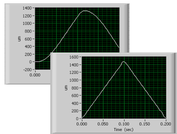
Full 1.5mm piezo scan showing enhanced dynamic
accuracy/reduced following-error from Dynamic Digital Linearization
A recent customer application spotlights this.  The application required rapid but very precise scanning over the full 1.5mm range of the P-629.1CD stage, with precise TTL signals from the nanopositioning controller at specific points in the waveform to trigger other instrumentation.  We approached this application using LabVIEW and DDL: First, the controller's internal waveform generator is enabled and the waveform parameters and TTL trigger-output specifications downloaded via our comprehensive standard set of LabVIEW subVIs, then waveform generation is commenced.  We used our digital controller's built-in data recorder capability to verify the impact of DDL in this application.  The figure shows the tracking performance of the loaded P-629.1CD before and after enabling DDL.

This has proven to be an enabling technology for this and other applications in fields as diverse as semiconductor metrology, defense and clinical life sciences, where rapid scanning requirements increasingly include previously unapproachable dynamic accuracies over long travels.

More information on Methods to Improve Piezo Dynamics

No comments:

Post a Comment