Punching Out A Novel Optical-Tweezer Calibration Technique

Consider: A punching bag is suspended by a spring.  A boxer pummels it, banging it from side to side in a chaotic, random way.  The boxer sways slightly from side to side.  You know the frequency and amplitude of his swaying.  From observing the anarchic path of the punching bag, can you determine the stiffness of the spring?

This is an exact analogy to a clever, insightful and astonishingly simple recent technique for calibrating the stiffness of an optical tweezer, the force-well formed by a tightly focused laser beam which is used to trap, manipulate and track microscopic dielectric beads in fluid-filled micro-chambers in single-molecule biophysics.  The coated beads can be hitched to molecular motors and DNA molecules, allowing the machinery of life to be illuminated.

Clearly, in order for an optical tweezer to be a quantitative tool, its force characteristics must be known.  One classical technique for calibrating a trap is to sweep the fluid chamber at constant velocity, back and forth, and observe the deviation of a trapped bead as the fluid drags it.  The trap force can be calculated by applying Stokes’ familiar hydrodynamic equation to the observed deflection of the bead.

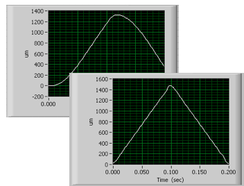
Dynamic Digital Linearization enables Stokes
calibration of optical tweezers by
eliminating following errors.
In theory, only the drag coefficient of the fluid and the diameter of the bead need to be known.  But this technique requires a sophisticated level of control of the piezoelectric microscope stage on which the fluid chamber is mounted.  The stage must perform a triangle wave motion, but the finite system bandwidths inherent in any electromechanical system ordinarily cause distortion of the actual waveform.  The corners of the positioning waveform become rounded, and following-error accumulates, meaning the stage position deviates from the desired instantaneous position as the waveform proceeds.  The overall amplitude of the waveform is rolled-off, and most importantly: the critical constant-velocity portion of the waveform isn’t as constant-velocity as needed.  Fortunately, the availability of Dynamic Digital Linearization has salvaged this technique for a generation of researchers.  With this unique technology, an advanced nanopositioning controller can virtually eliminate following-error in motions using its built-in waveform generator.  The Stokes calculations can be applied with confidence.

But back to our punching-bag.  Reduce it to the nanoscale, and it is our dielectric bead.  The pummeling boxer is Brownian motion, and his slight side-to-side sway is a nanoscale, sinusoidal position waveform applied to the fluid chamber by the piezoelectric microscope stage.  The spring is the optical trap.

If this can serve, then several advantages emerge versus the Stokes-calibration approach.  First, the sinusoidal waveform is a single frequency and can be selected to avoid driving structural resonances in the microscope assembly that might otherwise be problematic given the high-frequency Fourier components of the sharp-cornered triangle wave used in Stokes calibration.  Its amplitude is very small.  No constant-velocity region is required, and moderate following errors and rolloff are no issue since all needs to be known is the position-waveform amplitude in all axes, which a parallel-kinematic stage with direct motion metrology can provide.  And the analysis can be performed entirely in the frequency domain using the positional trace of the bead.  Brilliant!

From Fig. 2 of the Tolić-Nørrelykke paper, showing the
power spectral density of the bead's motion.
The technique was published as “Calibration of optical tweezers with positional detection in the back focal plane” in the Review of Scientific Instruments by Tolić-Nørrelykke, Schäffer, Howard, Pavone, Jülicher and Flyvbjerg after a collaboration which spanned Europe.  As they detail in their paper, the forces acting on the bead are well understood and separable: there is the chaotic Brownian motion, and then there is the drag-induced sinusoidal motion as the fluid chamber is oscillated at the nanoscale.  Observe the motion and calculate its power spectral density (PSD).  The PSD will show the white-noise spectrum of the Brownian motion, with a spike at the sinusoidal frequency.  From the power in the spike, the stiffness of the trap can be derived from the straightforward physics of a damped, simple harmonic oscillator.  The bead dimensions and fluid viscosity need not be known.


As an aside, there is a tantalizing resemblance between this PSD and the frequency-domain plot sometimes proffered as illustrating the positional resolution of some nanopositioning devices.  The difference is that this plot comes from actual motion data, not sensors indirectly inferring position via flexural strain deep in the mechanics.  (One could immobilize the platform of such a stage, and the sensors would still see strains as the piezos actuate.)  And the plot floor also represents actual limits—in this case, the inescapable Brownian motion of the bead—rather than filtered electrical strain-sensor noise, which is sometimes hyped to imply sub-picometer positional stability that is, unfortunately, not a possibility in the real-world ambient environment of any laboratory on Earth.  At the nano scale, we’re all punching bags.

(The author would like to thank Armin Hoffmann of the University of Alberta for bringing the Tolić-Nørrelykke paper to our attention.)


Best wishes--and a little gift!--from PI

Thank you for a productive year filled with fascinating applications.  Please enjoy our free Piezo University app from the Apple App Store and the Android Market!

Learn more on piezo motion basics

"The Imaging Suite is the Microscope"

Looking back at our publications in 2011, a favorite article was "Microscopy in 2011: The Imaging Suite is the Microscope," which appeared in American Laboratory.  It touched on some important themes, including key applications in super-resolution microscopy, recent advancements in fast focus automation, and the importance of software in instrumentation.

That last point, regarding the importance of software, is familiar to the point of obvious for users.  Software is the face of instrumentation to them.  When great hardware supports great software and vice versa, productivity results.  In contrast, hardware inadequately supported by software represents a frustrating waste of time for users.

Nowhere is this clearer than in the field of microscopy, where the classical limitations of optics are growing obsolete in the face of clever imaging and control techniques that tease resolution out of the application, and where the newly databased nature of discovery depends on coordinated, automated and networked control and communications of microscopes, staging and cameras.

We coined a phrase for this: "The Post-Rayleigh Era of Microscopy."

What this means: To the user, the face of the microscope is increasingly the computer screen.  The knobs and buttons are increasingly virtual.  The users themselves are increasingly remote.  And the images are increasingly the result of sophisticated image acquisition and processing algorithms.

As the article discusses, a corresponding lesson is that today, equipment manufacturers and their users are both participants in a larger ecosystem which includes software vendors-- and in microscopy's case that means providers of imaging suites like MetaMorph,  Micro-Manager and ScanImage.  Accordingly, forging partnerships with software developers has been a priority for us.  It's all in pursuit of productivity for our mutual customers.

Another reason the article was delightful for us was that American Laboratory, with its annual purchasing-plans surveys, was the very first publication to spotlight the advent of the personal computer as a top capital equipment line-item way back in the mid-'80s.  The cycle was propelled by instrumentation programming suites like National Instruments' LabVIEW, introduced in 1986, and which instituted a clever graphical flowchart paradigm for composing automated applications called virtual instruments.  NI's slogan was, "The Software Is The Instrument."

Indeed.  And the imaging suite is the microscope today.

Read more articles on precision motion systems for microscopy and imaging

Industry's first piezo physics App-- Free

Actual screen-snaps of the informative Piezo University app.
Available free for iOS & Android.

PI is the first nano/micropositioning company to offer its own informative, (mostly) non-commercial app for portable devices like the iPhone, iPad and Android phones and tablets.

Available free from the Apple App Store and the Android Market, the new Piezo University app offers illustrated glossaries, tutorials on piezo physics and mechanical design, and links to important industry resources.

All content is served live so it's always up-to-date and requires minimal storage. With its attractive, intuitive touch-enabled design and a wealth of thoughtful content, Piezo University deserves a place on your home screen.

More reading:
Piezo Motion Tutorial
Nanopositioning Basics

Hexapod Parallel Kinematics Update

There are many new developments for parallel kinematic multiaxis positioners.   The video below explains some of the differences between serial and parallel kinematics.


Other articles on hexapod applications can be found here.

See you at the Pathology Visions Conference

Digital pathology and telepathology are new weapons in fighting disease.  Its enablers are the Internet and microscopy automation.  At the Pathology Visions Conference in San Diego next week, we will be discussing key aspects of fast focus automation in particular.  Here's the abstract:

Advances in high-throughput, high-reliability focus automation for digital pathology

Scott Jordan
Director, NanoAutomation Technologies
PI (Physik Instrumente) L.P.
scottj@pi-usa.us

Broad adoption of digital pathology depends upon reliable and repeatable slide digitization.  In turn, repeatable/reliable whole slide imaging depends upon the ability to quickly find, hold and track focus. We discuss recent advances in piezoelectric focusing mechanisms and associated metrology of relevance to the community.

High-speed, high reliability focus optimization plays an important role in digital pathology by enabling faster capture of more repeatable images, by maintaining crisp focus during slide scanning motions, and by enabling real-time tracking over the acquisition intervals required by some emerging microscopy techniques. These attributes make focus automation a key variable in diagnostic concurrence.

Of the mechanical approaches available, piezo-actuator driven focus mechanisms combined with through-optic laser sensors offer the high-speed and high reliability required for meeting emerging demands. Piezo actuator driven mechanisms provide sub-millisecond response and can keep pace with throughput-driven methodologies.  Thus they can improve process economics in digital pathology as they have in applications like gene sequencing, semiconductor lithography and interferometric metrology.

Here we review:

  • Four types of piezo actuators
  • Reliability and speed capability of piezo actuator driven focus mechanisms
  • Focus detection technologies often used with piezo mechanisms
  • Examples of piezo deployment for high speed focus in other industries
  • Key metrics for evaluating and selecting focusing technologies
Read more articles on piezo motion devices

New Technology Enables Focusing from Afar

When most people hear the word "piezo" in the context of motion control, they understandably think of the classical piezoelectric stack actuator, composed of hundreds of thin layers of specialized ceramic interleaved with electrodes and sintered together.  When a voltage is applied, the stack expands.  Expansion is limited to about 1% of the stack length-- thus, a 100 mm long stack provide about 100 microns of travel.  Clever, frictionless lever amplifiers can be fabricated (usually using sophisticated wire electric discharge machining) to provide magnified travel.  In this way a compact piezo stage can provide hundreds of microns of travel.

This basic approach has served the microscopy industry well over our many years of manufacturing our popular PIFOC™ objective positioners, specialized linear motion devices optimized to tuck unobtrusively into a turret assembly while providing fast and straight axial positioning of the objective.  However, microscopes' dimensional constraints limit the amount of lever amplification such devices can incorporate.  400 microns has traditionally been the limit for PIFOCs in our catalog.

Until now.  Over the past several years, we've engineered new piezo technologies which provide much longer travels.  Rather than rely on the simple expansion and contraction of the ceramic element, our various piezomotors utilize either ultrasonic linear actuation or various approaches to walking actuation.  Each piezomotor principle has its inherent strengths for target applications but all provide theoretically unlimited travel, fieldless operation, high stiffness and holding force, nanoscale position-hold stability over long periods, and compact size.
N-725 PIFOC® is the first piezo-objective
drive with integrated NEXACT®
Piezo Linear Motor, combining
smooth motion, long travel ranges
and fast response with extreme position stability

Our NEXACT® motors, part of our PiezoWalk® family of ceramic motors, are an excellent example of all the above, plus sub-nanometer resolution.  Their small size and impressive force makes them ideal for long-travel objective positioning, and they are at the heart of our new N-725 NEXACT PIFOC Objective Positioner.  Offering a full 1 mm of travel, this unique mechanism offers high speed and maintenance-free operation.  Its long travel helps accommodate varying substrates and easy load/unload operations, making it ideal for automation applications.  And now it is available in systems integrating the Motion X FocusTrac™Autofocus Sensor for especially responsive and crisp autofocus actuation.


N-725 tracking focus of
a disk spinning at 300 RPM
Meanwhile, autofocus is now a capability which spans almost all PI motion device and controller combinations.  Ease-of-use, stability, speed, applications flexibility and reliable focus capture from extreme out-of-focus conditions were notable design targets accomplished with all configurations.  Systems integrating N-725 meet all these criteria over the full 1mm range of the device.  Its sophisticated, all-digital E-861 Controller/Driver offers USB and RS-232 connectivity together with TTL utility and trigger lines and a joystick port.  And, as a PI General Command Set device, it is supported by a wealth of proven software development tools and the leading microscopy suites.

Fast, automatic focus capture
from 900 microns out of focus!
A special capability is Fast Focus & Freeze (F3), PI's exclusive ability to capture and track the focal plane and then bumplessly switch to nanoscale-stable position-hold, with the ability to precisely position the objective with respect to the focal plane using the device's integrated position sensor.  This is an invaluable capability for high-throughput automated Z sectioning and other quantitative studies where the focal plane serves as a datum plane.  With N-725, F3means the initial condition can be up to 1 mm out of focus.

Count the enablers: unprecedented travel, easy integration, high responsiveness, fast actuation, robust focus-capture and tracking, and Fast Focus & Freeze.  N-725 is a revolutionary addition to the microscopist's toolkit.